Blog
ISO 1328 Gear Accuracy Grades A Practical Guide for Precision Applications


ISO 1328 Gear Accuracy Grades: A Practical Guide for Precision Applications
When a gear drawing calls for an ISO 1328 gear accuracy grade, the requirement covers more than one number. It sets a framework for checking tooth spacing, tooth form, tooth alignment, radial runout, and related transmission errors. The grade helps a buyer and a gear manufacturer use the same language when they discuss quality.
The right grade depends on the gear’s size, speed, load, noise target, heat treatment, and finishing process. A small high-speed EV gear may need tighter control of tooth form and lead than a larger, slower industrial gear. This guide explains what ISO 1328 measures, how manufacturing affects the result, and how to write a practical requirement for a precision gear project.The EV precision gear range provides context on the application areas.
What ISO 1328 Defines
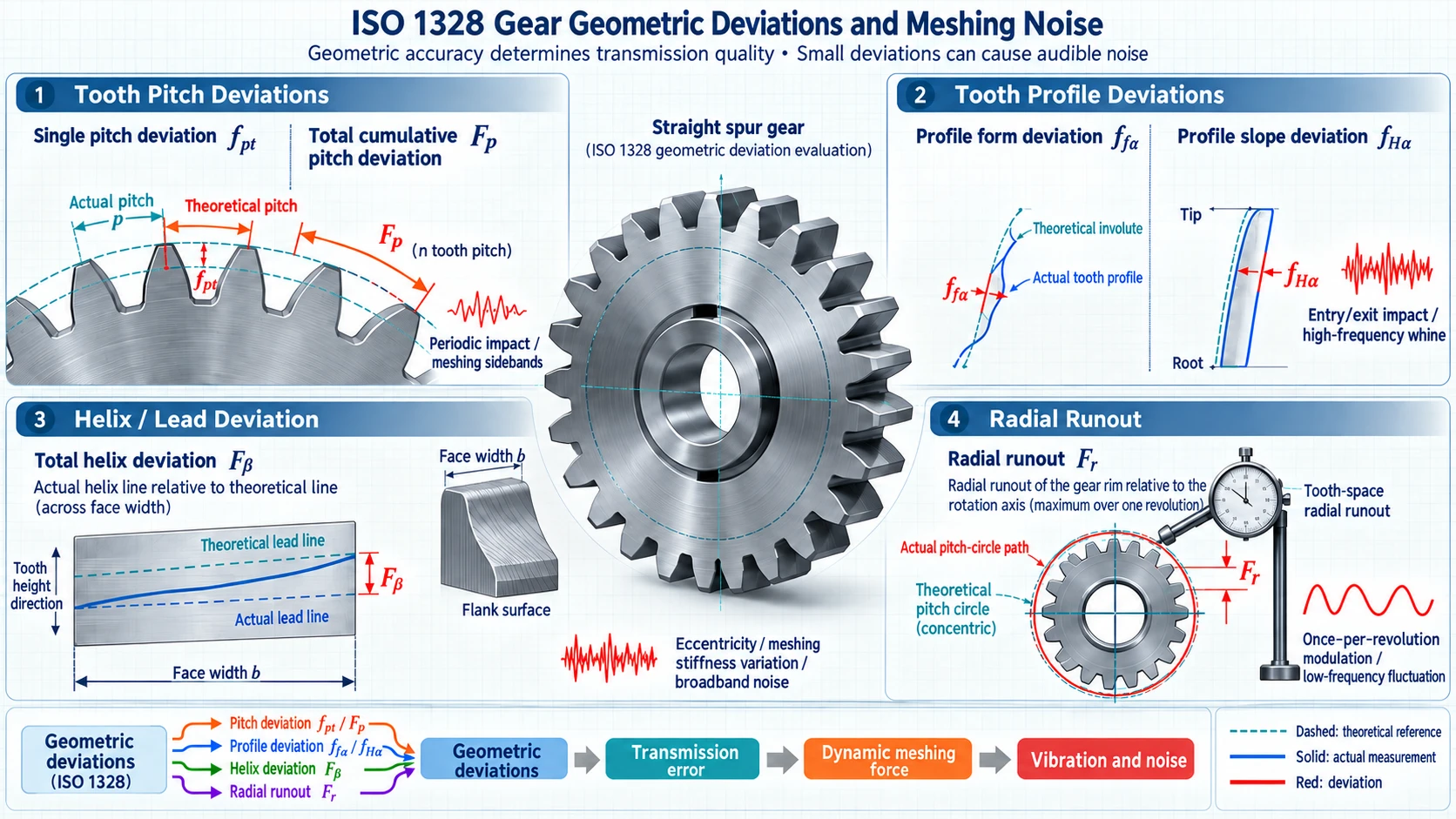
ISO 1328 provides a system for evaluating the accuracy of cylindrical gears. It separates several types of geometric error so a measurement report can show where a gear meets its target and where it needs attention.
A gear can have accurate tooth spacing and still show a problem in tooth form. It can also have a good profile but a lead error caused by alignment, cutter setup, heat treatment, or grinding. Looking at the grade alone hides these differences. A useful report links each result to the measurement method, datum, gear size, and inspection condition.
The standard is most useful when the drawing and the inspection report use the same terms. Before placing an order, define the applicable ISO 1328 edition, the required grade, the inspection locations, and the acceptance rule for the batch.
How ISO 1328 Gear Accuracy Grades Work
ISO 1328 grades describe the permitted level of geometric error for a gear. The grade number is one part of the requirement. The actual tolerance also depends on the reference diameter, module, tooth count, face width, and other gear dimensions used by the standard.
A smaller permitted error corresponds to a tighter manufacturing requirement. That usually calls for better machine condition, controlled datum surfaces, stable heat treatment, and a finishing process such as grinding or honing. A tighter grade can raise production cost and inspection time, so it should match the function of the gear.
Grade Selection Depends on More Than the Number
Start with the operating conditions. Record speed, torque, load reversals, duty cycle, service life, lubricant, temperature, and the noise target. Then review the gear geometry, including module, tooth width, pressure angle, helix angle, root fillet, contact ratio, and shaft arrangement.
These details affect which errors matter most. At high speed, periodic pitch error and profile variation can increase transmission error and mesh noise. In a narrow gear, lead error can reduce the contact area. In a heavily loaded gear, poor alignment can move the contact pattern toward the tooth edge and raise local stress.
The mating gear and the housing also affect the result. Bearing clearance, shaft deflection, center distance, assembly runout, lubrication, and tooth modifications can change the working contact even when a gear passes its shop inspection. ISO 1328 gives a geometric quality framework; it does not replace a complete system validation.
Common Accuracy Priorities by Application
EV e-axle gears often combine high rotational speed, rapid torque changes, compact packaging, and a quiet vehicle environment. The project may therefore place close limits on profile, lead, pitch variation, runout, and surface finish. The chosen grade should follow the drive unit’s noise, efficiency, durability, and production targets.
Robot joint gears and precision reducers also need controlled transmission error and repeatable backlash. Industrial gears may accept a wider geometric tolerance when speed and noise requirements are lower, although heavy loads still require control of tooth contact, lead, and runout.
These examples describe selection priorities rather than a universal grade table. The gear designer and supplier should confirm the grade after checking the complete geometry and manufacturing route.
The Main Measurement Items
An ISO 1328 gear report becomes easier to use when each result is tied to a physical effect in the gear mesh.
Tooth Pitch Deviation
Pitch deviation describes the spacing error between successive teeth or between a measured tooth and the theoretical position. Accumulated pitch error can produce a repeating change in mesh timing. On a high-speed gear, that change may appear as vibration or gear whine.
Check whether the report lists single pitch deviation, cumulative pitch deviation, or both. The drawing should also state the measurement direction and the reference datum so different suppliers produce comparable data.
Profile Deviation
Profile deviation compares the working tooth curve with the theoretical involute. It can reflect errors in cutting, heat treatment, grinding, tool condition, or the selected profile modification.
Profile form error and profile slope error do not have the same effect. A local deviation near the tip may affect entry and exit of contact, while a broader slope error can change load sharing across the tooth. The report should show the evaluation range and any designed tip relief or root relief.
Helix Deviation
Helix, or lead, deviation describes how the tooth runs across the face width. Lead error can come from machine alignment, part mounting, thermal movement, shaft deflection, or distortion during heat treatment.
A gear with excessive lead deviation may carry load on one side of the face. This reduces the effective contact width and can increase edge stress. For helical gears, the drawing should state the helix direction, face width, datum, and lead modification where applicable.
Radial Runout
Radial runout measures the variation of tooth or pitch-cylinder position as the gear rotates around its datum axis. Runout can result from the bore, reference diameter, clamping method, cutting process, or heat-treatment movement.
Runout changes the center distance during rotation and can add to transmission error. Measuring the gear from the same datum used in assembly makes the result more useful than a measurement taken from an unrelated surface.
Total Composite Deviation
Composite tests evaluate the gear while it meshes with a master gear or a defined reference. They combine several geometric effects into a functional result. This type of test can reveal how the gear behaves in mesh, while single-error measurements help identify the source of a problem.
Use composite results with profile, lead, pitch, and runout data. One result should not replace the others when the project requires root-cause analysis or process control.
Tooth Thickness and Backlash
Tooth thickness controls the working clearance between mating gears. Backlash must allow lubrication, thermal growth, manufacturing variation, and assembly movement. Excessive backlash can increase impact and noise; insufficient backlash can cause binding when temperature or alignment changes.
State the tooth-thickness method, measurement location, temperature, and datum. The gear accuracy grade does not by itself define the complete backlash requirement.
How Manufacturing Processes Affect Gear Accuracy
Gear accuracy develops through the whole process chain. Hobbing, shaping, turning, shaving, grinding, honing, and inspection each influence the final result. Tool wear, machine alignment, fixture repeatability, and datum quality can leave different signatures in the report.
The precision gear manufacturing process explains how forming, cutting, heat treatment, grinding, and inspection can be arranged for a project.
Heat treatment adds another source of variation. Carburizing and quenching can change tooth size, lead, runout, and profile. Induction hardening concentrates heat in selected zones and requires control of coil position, scanning, and cooling. Nitriding usually causes less thermal distortion, yet the core condition and the thin hardened layer still need verification.
Heat Treatment and Grinding Allowance
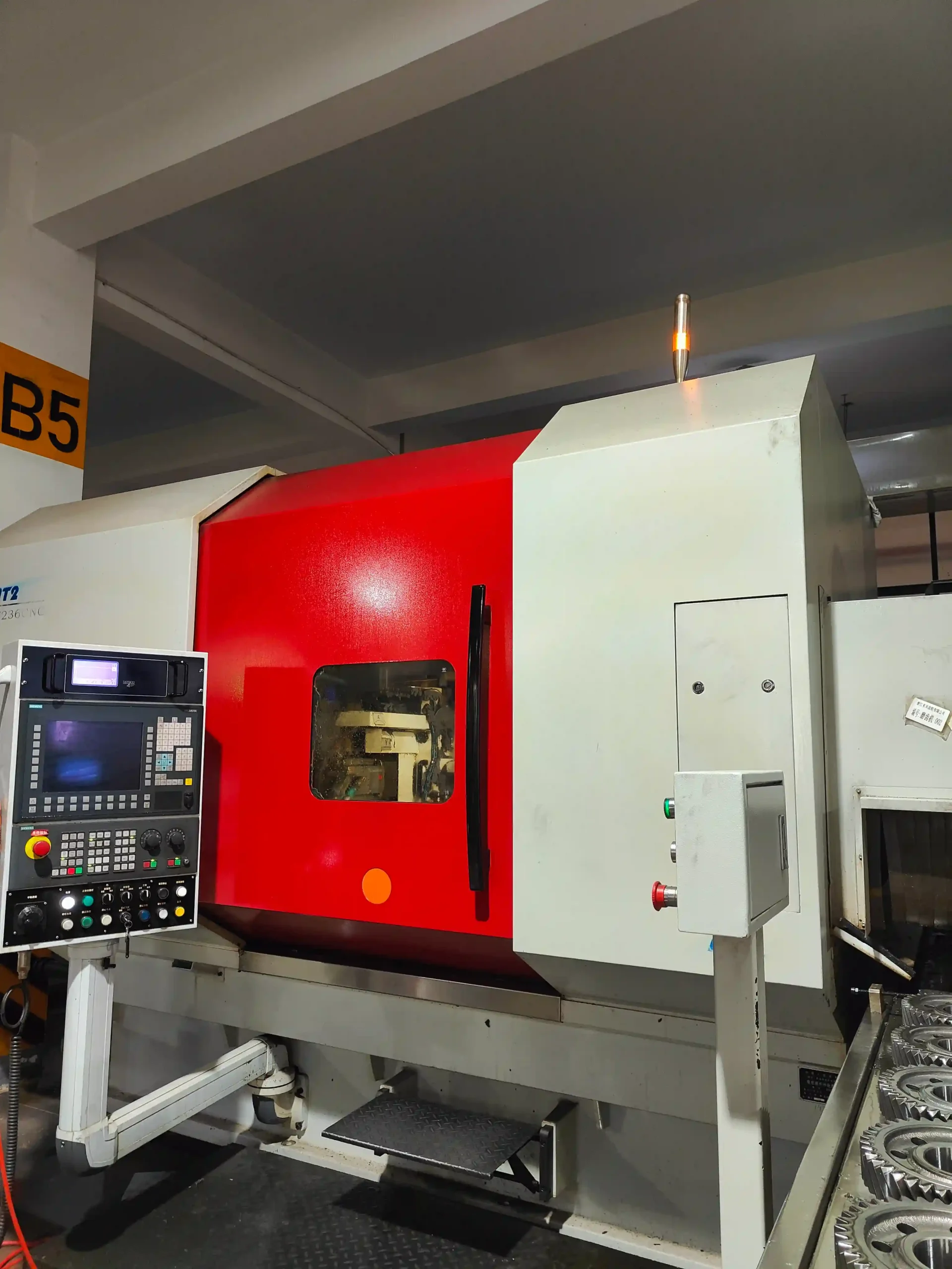
Set the grinding allowance before heat treatment. The allowance must cover expected growth, taper, runout, and tooth-form change without removing the intended case or changing the designed geometry. Fixture design and quench transfer time also affect distortion.
A practical process plan connects blank inspection, pre-treatment, machining, heat treatment, grinding, cleaning, and final measurement. Checking hardness alone cannot show whether the gear meets its accuracy requirement.
Gear Accuracy After Finishing
Final ISO 1328 inspection should take place after the last operation that can change tooth geometry. For a ground gear, that normally means measuring after grinding, deburring, cleaning, and temperature stabilization. Record tooth form, lead, pitch, runout, tooth thickness, surface condition, and the applicable accuracy grade.
The report should identify the instrument, calibration status, measurement temperature, datum, evaluation range, and inspection sample. These details let the buyer compare results across batches and investigate a change in the process.
How to Specify ISO 1328 on a Gear Drawing
A clear drawing gives the supplier enough information to plan production and gives the inspector a defined acceptance rule. Include:
- The applicable ISO 1328 edition and part.
- The required accuracy grade.
- Profile, lead, pitch, and runout limits.
- Tooth thickness, backlash, or measurement-over-pins requirements.
- Datums, inspection direction, and evaluation range.
- Material, heat treatment, hardness, and case-depth requirements.
- Grinding allowance and final surface condition.
- Sampling frequency, batch definition, and reporting format.
If the gear operates in a sensitive noise application, add the transmission-error, surface-finish, balance, and functional test requirements that the system team has approved. These requirements sit alongside the ISO 1328 grade.
How to Choose the Right ISO 1328 Gear Grade
Use a staged review rather than selecting a grade from a catalog alone. First, define speed, torque, life, temperature, lubrication, and noise limits. Next, confirm gear geometry, shaft features, packaging, and load distribution. Then compare candidate material and treatment routes, such as carburized 20CrMo, induction-hardened 42CrMo, or nitrided 38CrMoAl when those routes suit the design.
Review the expected contact stress, tooth-root stress, case depth, distortion, machining stock, and finishing capability. Ask the supplier which cutting and finishing operations can hold the proposed grade and how the supplier will measure it. Validate samples with dimensional, accuracy, hardness, case-depth, surface, and functional checks before releasing a mass-production process.
DD Gear’s Approach to Precision Gear Manufacturing
DD Gear produces small-module, precision metal gears for EVs, robotics, AGVs, and intelligent automation. Its work can cover input shaft gears, parking-end gears, main reduction gears, and drive motor shafts. These applications require the gear drawing, material, heat treatment, tooth geometry, accuracy target, and inspection method to work as one specification.
FAQ
Q1: What does an ISO 1328 gear accuracy grade mean?
A: It defines a permitted level of geometric error for a cylindrical gear. The grade works with the gear’s size, module, tooth width, and specified measurement method.
Q2: Which ISO 1328 gear grade is suitable for EV e-axle gears?
A: The suitable grade depends on speed, torque, noise target, gear size, heat treatment, and finishing process. Select it after reviewing the complete drive-unit requirements rather than using one grade for every EV gear.
Q3: Does a higher ISO 1328 gear grade always reduce noise?
A: A tighter geometric grade can reduce one source of transmission error. Noise also depends on tooth microgeometry, surface finish, alignment, bearings, housing stiffness, lubrication, and dynamic balance.
Q4: How does heat treatment affect ISO 1328 gear accuracy?
A: Heating and quenching can change tooth size, profile, lead, runout, and alignment. The process plan should include distortion allowance, fixturing, machining stock, and post-treatment finishing.
Q5: What should a buyer include in an ISO 1328 gear drawing?
A: Include the ISO 1328 edition and grade, gear dimensions, profile and lead limits, pitch and runout requirements, tooth thickness or backlash, datum, material, heat treatment, hardness, finishing allowance, inspection method, and batch acceptance rule.